


How does the locking mechanism of the hydraulic quick connector prevent accidental disengagement?
Release Time : 2025-06-03
The locking mechanism of the hydraulic quick connector is the core design to ensure its safety and reliability in high-pressure fluid transmission. Its function of preventing accidental disengagement is achieved through the synergy of multiple structures. These mechanisms not only need to deal with external interference such as mechanical vibration and pressure fluctuations, but also adapt to the operation requirements of frequent plugging and unplugging, and maintain stability in long-term use. The common locking method is mainly mechanical clamping, supplemented by fluid pressure. Through the precise geometric structure design, the connector forms a firm locking state after being plugged in, avoiding connection failure due to external force collision or system vibration.
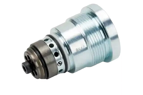
Ball locking is a more typical structure in hydraulic quick connectors. Its principle is to evenly distribute a number of balls on the inner wall of the outer sleeve or sleeve of the connector. When the male connector is inserted into the female connector, the outer sleeve is displaced by the axial force, and the balls are pressed into the annular groove of the male connector to form a clamping state. The key to this structure is the matching accuracy of the ball and the groove. The taper of the groove and the hardness of the ball must be accurately calculated to ensure that the ball will not be deformed or fall off due to excessive force when subjected to system pressure, and can smoothly exit the groove when the outer sleeve is unlocked. To prevent the jacket from loosening due to vibration, some designs will add springs or limit devices to the jacket to provide additional axial resistance and ensure the continuity of the locking state.
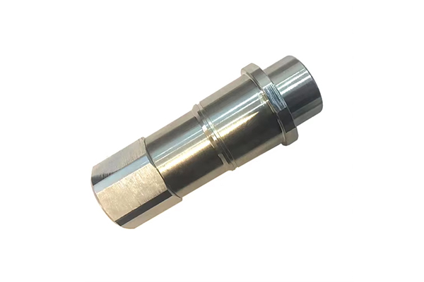
The snap-on locking mechanism is connected through the protrusions and slots set at the ends of the male and female connectors. When the male connector is inserted into the female connector, the snap on the end slides into the slot through elastic deformation. After it is in place, the snap is reset and tightly engaged with the inner wall of the slot to form a mechanical lock. The advantage of this structure is that it is easy to operate. No additional tools are required when plugging and unplugging. You can judge whether the connection is in place by feel alone. In order to enhance the anti-slip performance, the snap is usually designed with a symmetrically distributed multi-petal design. There is a certain elastic gap between the petals of the snap, which can adapt to slight angle deviations and press against each other under pressure to prevent the single-petal snap from breaking due to uneven force. In addition, the material of the snap is mostly high-strength engineering plastics or metal alloys. The surface hardening treatment improves the wear resistance and extends the service life of the locking structure.
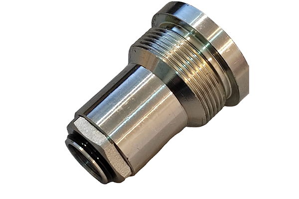
Threaded locking is a traditional but reliable method. The outer side of the male connector is provided with an external thread, and the inner side of the female connector is provided with an internal thread. When connected, the male and female connectors are screwed together and fixed by rotating the outer sleeve. The anti-slip performance of this mechanism mainly depends on the self-locking characteristics of the thread. Usually, fine pitch threads are used to increase the contact area and friction. At the same time, sealants are filled in the thread gap or O-rings are set to prevent fluid leakage. In order to prevent the thread from loosening due to vibration, some connectors will add locking nuts or anti-loosening washers at the end of the thread to further fix the connection state through mechanical limit. The disadvantage of threaded locking is that the plug-in and pull-out speed is slow, but because of its high connection strength, it is often used in high-pressure or ultra-large flow hydraulic systems.
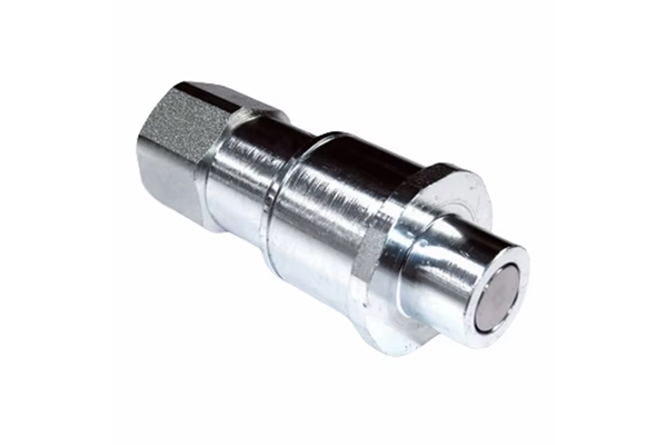
The pressure-assisted locking mechanism uses the pressure of the hydraulic system itself to enhance the connection stability. When the connector is plugged in, the system starts and builds pressure. The fluid pressure will act on the internal piston or sealing ring of the male and female connectors, generating additional axial thrust to further compress the two. This design is particularly suitable for high-pressure working conditions, because the higher the system pressure, the greater the locking force, forming a dynamic balance of "the greater the pressure, the tighter the connection". For example, in the hydraulic system of some dump trucks, the internal piston of the hydraulic quick connector will expand under the action of oil pressure to fill the tiny gap between the male and female connectors. At the same time, the toothed structure on the edge of the piston engages with the groove on the inner wall of the connector to form a double lock of mechanical and fluid pressure, effectively resisting the vibration impact caused by bumpy roads.
Dustproof and lubrication design are equally important to the reliability of the locking mechanism. In the field operation environment, impurities such as dust and soil can easily enter the interior of the connector and adhere to the surface of the locking structure, causing the outer sleeve or thread to stagnate, and even wear key components such as balls and buckles. Therefore, many hydraulic quick connectors are equipped with dust covers or sealing rings at the locking parts to prevent impurities from invading. At the same time, internal moving parts such as the sliding surface of the outer sleeve and the ball track will be coated with long-term grease to reduce friction resistance and avoid structural deformation caused by dry grinding. Grease can also buffer vibration impact to a certain extent, reduce fatigue wear of locking components, and maintain the smoothness and reliability of the connection.
Human operation factors are also the key to affecting the effect of the locking mechanism. The correct plug-in and pull-out operation process can maximize the performance of the locking structure. For example, when inserting the connector, ensure that the male and female ends are aligned to avoid tilted insertion that may cause deformation of the buckle or ball. When pulling out, release the system pressure first and then operate the unlocking device to prevent damage to the locking structure during disassembly under pressure. Regular maintenance inspections are also important. Observe whether the jacket, buckle and other parts are worn or cracked, whether the threads are loose, and replace aging seals and grease in time to ensure that the locking mechanism is always in the best working condition. In addition, operator training is also indispensable. Being familiar with the characteristics and maintenance requirements of different locking methods can effectively reduce the risk of accidental disengagement due to misoperation.